
Description
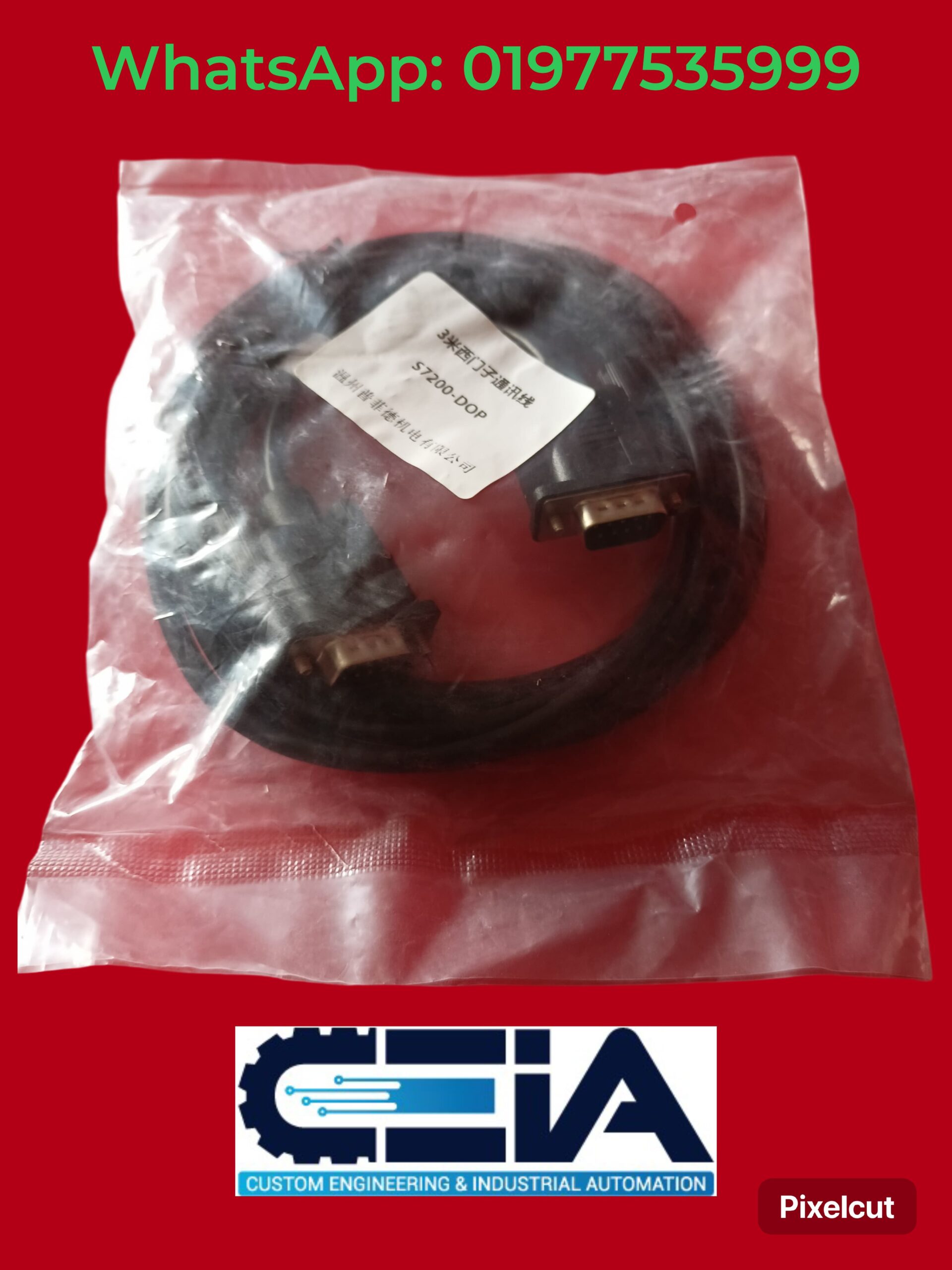
The Delta HMI to Siemens S7-200 PLC communication cable (Model: S7200-DOP) is designed to establish a serial data link between Delta’s DOP-series Human Machine Interfaces (HMIs) and Siemens’ S7-200 PLCs. This cable enables configuration, monitoring, and control of the Siemens PLC through the Delta HMI. Below are the key details:
Key Features & Compatibility
-
Compatibility:
-
Delta HMI: Compatible with DOP-B series (e.g., DOP-B07S, DOP-B10S) and other DOP models with RS-485/RS-232 ports.
-
Siemens PLC: Works with S7-200 series (e.g., CPU 224, CPU 226) via the PPI/RS-485 port.
-
-
Interface:
-
HMI Side: Typically uses a 9-pin RS-232 or RS-485 port (depending on the HMI model).
-
PLC Side: Connects to the Siemens S7-200’s 9-pin D-Sub RS-485 port (PPI port).
-
Cable Type: Acts as a protocol converter or physical adapter to bridge Siemens PPI/Modbus and Delta HMI communication protocols.
-
-
Communication Protocol:
-
Configure the Delta HMI to use Modbus RTU (Siemens S7-200 supports Modbus via its自由口通信 (Freeport) or libraries like Modbus Slave).
-
Ensure matching baud rate, parity, and data bits on both devices.
-
Wiring Configuration
The cable connects the RS-485 pins of the Siemens PLC to the RS-485/RS-232 pins of the Delta HMI. Below is a typical RS-485 2-wire setup:
| Siemens S7-200 (9-pin D-Sub) | Delta HMI (9-pin RS-485) |
|---|---|
| Pin 3 (RS-485 B/–) | Pin B (Data–) |
| Pin 8 (RS-485 A/+) | Pin A (Data+) |
| Pin 5 (GND) | Pin 5 (GND) |
Notes:
-
For RS-232 connections on the HMI side, use an RS-232 to RS-485 converter.
-
Add a 120Ω termination resistor across A/B lines if the cable is long (>50m).
-
Shield the cable and ground the shield at one end to reduce noise.
Software Configuration
-
Delta HMI (DOPSoft/DOPSoft Pro):
-
Select Modbus RTU as the communication protocol.
-
Set parameters:
-
Baud Rate: 9600, 19200, etc. (match PLC settings).
-
Data Bits: 8.
-
Parity: Even/Odd/None (must match PLC).
-
Station Address: PLC Modbus address (e.g., 1).
-
-
Map HMI elements (buttons, displays) to Siemens PLC registers (e.g., V, M, Q addresses).
-
-
Siemens S7-200 PLC:
-
Use STEP 7-Micro/WIN to configure the PLC’s communication port:
-
Set Port 0/1 to Freeport Mode with Modbus RTU parameters.
-
Load a Modbus Slave Library (if required) to enable Modbus communication.
-
-
Ensure PLC register addresses align with HMI addressing (e.g., V-registers in Siemens map to 4xxxxx addresses in Modbus).
-
Typical Applications
-
Real-time monitoring of PLC data (e.g., temperature, pressure).
-
Control of PLC outputs (e.g., motors, valves) via HMI touchscreen.
-
Alarm management and historical data logging.
Troubleshooting Tips
-
No Communication:
-
Verify wiring polarity (swap A/B if needed).
-
Check for matching baud rates and parity settings.
-
Ensure the PLC’s Modbus library is correctly initialized.
-
-
Intermittent Data:
-
Add termination resistors and check cable shielding.
-
Reduce cable length or use repeaters for long distances.
-
-
Address Mismatch:
-
Confirm Modbus address mapping (e.g., Siemens V100 maps to Modbus 40101).
-
Alternatives
-
Ethernet Communication:
-
Use a Siemens CP243-1 (Ethernet module) for S7-200 and configure the Delta HMI for Modbus TCP.
-
-
Protocol Converters:
-
Deploy a standalone Modbus RTU to PPI converter for seamless integration.
-
Required Components
-
Delta HMI Software: DOPSoft or DOPSoft Pro.
-
Siemens PLC Software: STEP 7-Micro/WIN (for PLC configuration).
-
Cable: Custom S7200-DOP cable or DIY wiring as per pinout above.


Reviews
There are no reviews yet.